top of page

Basilisk
UCF's Most Powerful RSO Liquid Bi-Propellant Rocket
August 2023 - May 2024
Role: Aerostructures Manager
Organization: Knights Experimental Rocketry
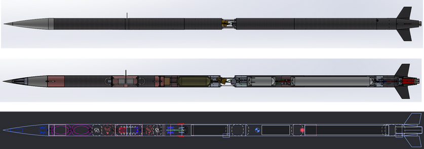
CAD and OpenRocket epresentation of Basilisk
Basilisk was the second iteration of a liquid bi-propellant rocket designed by a Registered Student Organization from the University of Central Florida. This project built upon the foundation of our previous project, Valkyrie. Basilisk was designed to compete at the Friends of Amateur Rocketry (FAR) in the FAR-Unlimited (Previously known as FAR-51025 Unlimited). The FAR- Unlimited competition was a combined points and altitude-based competition, and was scored based on several criteria. We chose to do another bi-propellant rocket, as liquid rockets would have the largest score boost. We also chose to have a deployable payload, external cameras, live telemetry, and a deployable water ballast in the nose cone.
More information on the competition and team breakdown can be found below in the Vehicle CDR slides:
Basilisk was one of the largest projects in the club's history. Our previous success with Valkyrie created a great deal of hype and interest in its successor. The project as a whole contained over 90 active members, with the propulsion system making up nearly half of all members. My airframe team was nearly triple the size of the team I led on Valkyrie. This created a unique and engaging opportunity to grow my leadership skills and provide the best environment I can for designs to flourish.

Basilisk Team at an Integration Meeting

Aerostructures Team at PDR

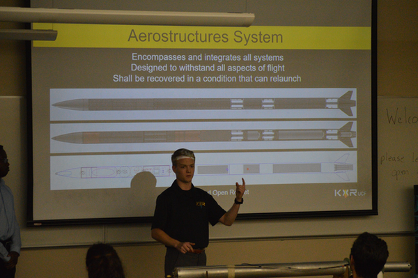
Aerostructures Team at CDR
To handle such a large team, I chose to break down the system into 5 sub-systems:
Flight Dynamics | Led by Nicholas Piakis: Managed the overall ballistics of flight, fins and stability, airframe-specific payloads.

Flight Dynamics Team at CDR
Recovery | Led by Diego Alvarez: Managed the recovery system, main payload deployment, and external attena and avionics integration.

Recovery Team at CDR
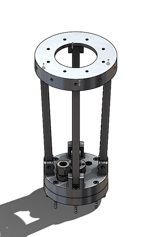
Internal Structures | Led by Vladimiro (Alex) Lozano: Managed all internal structures, main integration points, and hardware with other systems, thrust structure, and coupling chassis.

Internal Structures Team at CDR
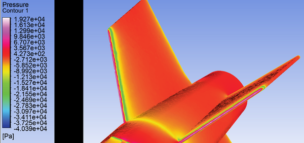
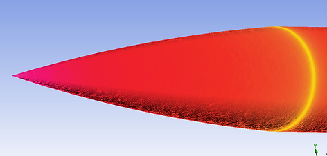
Aerodynamic Structures | Led by Devon Terry: Managed all external aerodynamic features, nosecone optimization, external shrouds, and full vehicle sims.
Aerodynamic Structures Team at CDR
Manufacturing (Gals) | Led by Kaela Hollister: Created manufacturing process, led manufacturing events, created jigs and molds for large scale composites.

Manufacturing Team at CDR
Simulation Guru | Harmon Estes: Oversaw and ran the majority of ANSYS Fluent and ACP sims. Validated hand calculations and composite layups.


Screenshots from the Calculator
The original calculator can be found below. But be warned, it is a rather large excel sheet.
The airframe was designed over the fall semester and passed through two major milestones. The first was a Preliminary Design Review (PDR), which was the checkpoint to evaluate the overarching design requirements and solutions. The second was the Critical Design Review (CDR), this presentation aimed to capture the final designs of the subsystems and the next steps for manufacturing in the airframe in the spring. We also ended up having a Delta CDR in the spring, which focused on addressing any lackluster designs or comments from the upper directors of the club.
In the end, Basilisk stood tall at over 18ft tall, at 145lb wet mass. Our team designed the airframe to handle speeds around 0.6 Mach. The airframe sported several unique features as seen below:

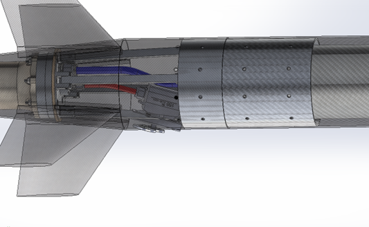
Accessible body tube couplers, allowing easy access to the fluid systems components.
Thrust structure that allowed the fin section to be removable before flight for ease of integration and motor accessibility.
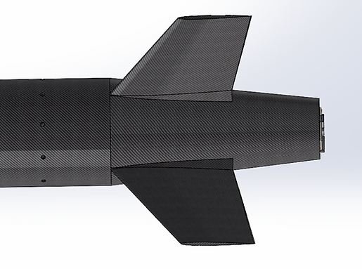
Aerodynamic Boat tail, decreasing base drag and integrating the fins into the main structure.

Von-karmin nosecone with integrated and deployable water ballast.
More information about the design and technical aspects can be found the the slide decks below. While the information provided may not be the most technically up-to-date or industry standard, I am proud of the work my team did, as a majority of these designs involved new challenging topics for them.
Another exciting endevor of this project was our ambition to use a more complex and high-performance manufacturing method for our carbon fibre composites. Previously in the past our team utilized a wet lay-up composite technique. This involved hand portioning epoxy onto dry carbon fibre. While not the most precise manufacturing technique, its relatively low technical entry level provided a solution to previous project cycles. This time around, however, our team opted to use pre-impregnated carbon fiber composites, or pre-preg for short. Pre-preg requires the carbon to be kept at a cold temperature until use to avoid curing, and needs to be brought up to pressure and temperature for an extended time to cure. This requires the use of an autoclave, to which access was graciously provided by a research lab on campus.
The choice to use pre-preg also involved more precise tooling and manufacturing processes. To ensure concentric airframe tubes to the length needed, we ordered a new mandrel and created a mandrel stand to ensure the correct application of carbon fibre during the lay-up process. Below are photos of the lay-up process and manufacturing of the main airframe body tubes.
Machined Mandrel

Application of a Mold Release Pre-Carbon Lay-up

Pre-Preg Application

Release Film Application
Surface Finish Layer

Breather Cloth and Vaccume Bag

Vaccum Sealed and Place into Autoclave

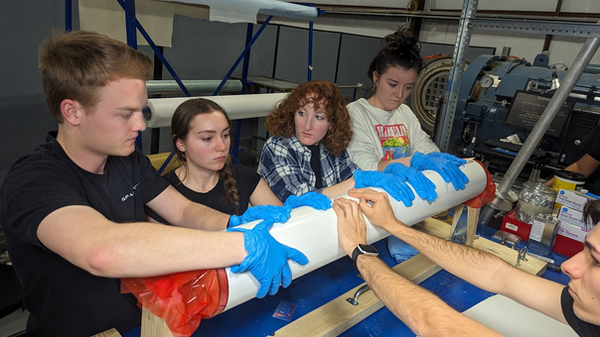
Part of the Aerostructures Team During One of Many Manufacturing Sessions
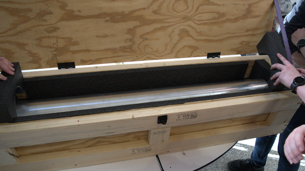
In total, 5 airframe tubes were created, all designed and manufactured by my team. We also wet-laid a fibreglass nosecone and planned to create another iteration of our previous boat tail design.
Our team was nearing the finish line for the manufacturing season when we were forced to stop and drop our project. A sister project within the club suffered an anomaly during a static fire. While the nature of the anomaly was not unexpected for hybrids, the events surrounding the static fire and the lead-up to the day of resulted in repercussions (understandably and rightfully). This caused the club as a whole to stop all work and refocus on righting the wrongs. Tragically, Basilisk never got to see the light of day. Hundreds of long hours, countless memories, and the passion of our team was cut short.
While myself and other members of the team were disheartened to have to put down our passion for Basilisk, I believe it was an important opportunity to reflect on how we went about doing things. A large portion of our work was done near the last minute due to unreasonable timelines, and untested designs and processes that were being allowed to continue. We repeated mistakes that many teams of passionate and dedicated engineers make when they are improperly strained with timelines or goals.
Throughout it all, through the thick and thin, I am honored to have worked alongside such great friends and young engineers. Although we never got to see Basilisk take to the sky, its impact on my engineering experience will always be remembered.
bottom of page